Vivado Design Flows: Project Mode
In this post we discuss the Vivado Use Models (Project vs Non-Project Mode) and create a design in Project Mode.

Vivado's Project and Non-Project Mode provide very different user experiences when working with our FPGA designs. Understanding the advantages and disadvantages of each one will help us choose the use model that better suits us, and will help make the development process more enjoyable.
By the end of this two-part tutorial, we'll understand the differences between the Project and Non-Project Mode, both at a conceptual level, and by setting up the same project using both strategies.
Project vs. Non-Project Mode
Vivado offers two modes for handling FPGA designs: Project Mode and Non-Project Mode.
In Project Mode, Vivado manages source files and design status, generates and stores results and reports for each stage of the design, and supports advanced analysis capabilities, most notably the ability to cross-probe signals across design stages. In Project Mode, the design is managed with a project file stored on disk and updated across multiple work sessions.
In Non-Project Mode, the designer is responsible for managing source files, generating, and storing results and reports for each design stage. In Non-Project Mode, Vivado creates a minimal project in the PC's memory, which is deleted when the tool is closed.
The choice between Project and Non-Project Mode comes down to control versus convenience. The Non-Project Mode offers total control over the development flow, but the designer is solely responsible for managing the design. On the other hand, the Project Mode has many convenient design management and analysis features, but it limits the designer's control over the development flow.
GUI vs Command Line
One common misconception is that the Project Mode is intended for use with the GUI, while the Non-Project Mode is designed for use with the command line. This is not the case: both the Project and Non-Project Modes can be fully utilized from the command line, and both support batch (script-based) and interactive (single-command) execution.
The use of the GUI is a bit more nuanced. The Project Mode provides full support for GUI interactions and includes analysis tools that work across various design stages. On the other hand, the Non-Project Mode supports GUI interaction only through design checkpoints, whose scope is limited to the design stage in which they have been generated.
Design Files
Regardless of whether we use the Project or Non-Project Mode, there's a minimal set of input files required for an FPGA project: the design files, the constraint files, and the simulation files.
The design files describe the logic that we'd like to implement on the FPGA. These are usually RTL sources in Verilog or VHDL, though they often include proprietary file formats for IP cores and embedded processors.
The constraints files describe non-logical properties of our system. At a minimum, the constraints include the clock signals in our design and the assignment of IO signals to the physical pins of the FPGA device.
Finally, the simulation files enable us to model the behavior of our logic within a simulator running on the PC, which helps verify the correctness of our design. Running a simulation is not strictly necessary for getting a design up and running on an FPGA, but it is highly encouraged and a common practice in professional FPGA development.
The image below illustrates a minimal folder structure for an FPGA design, incorporating the input files described above.
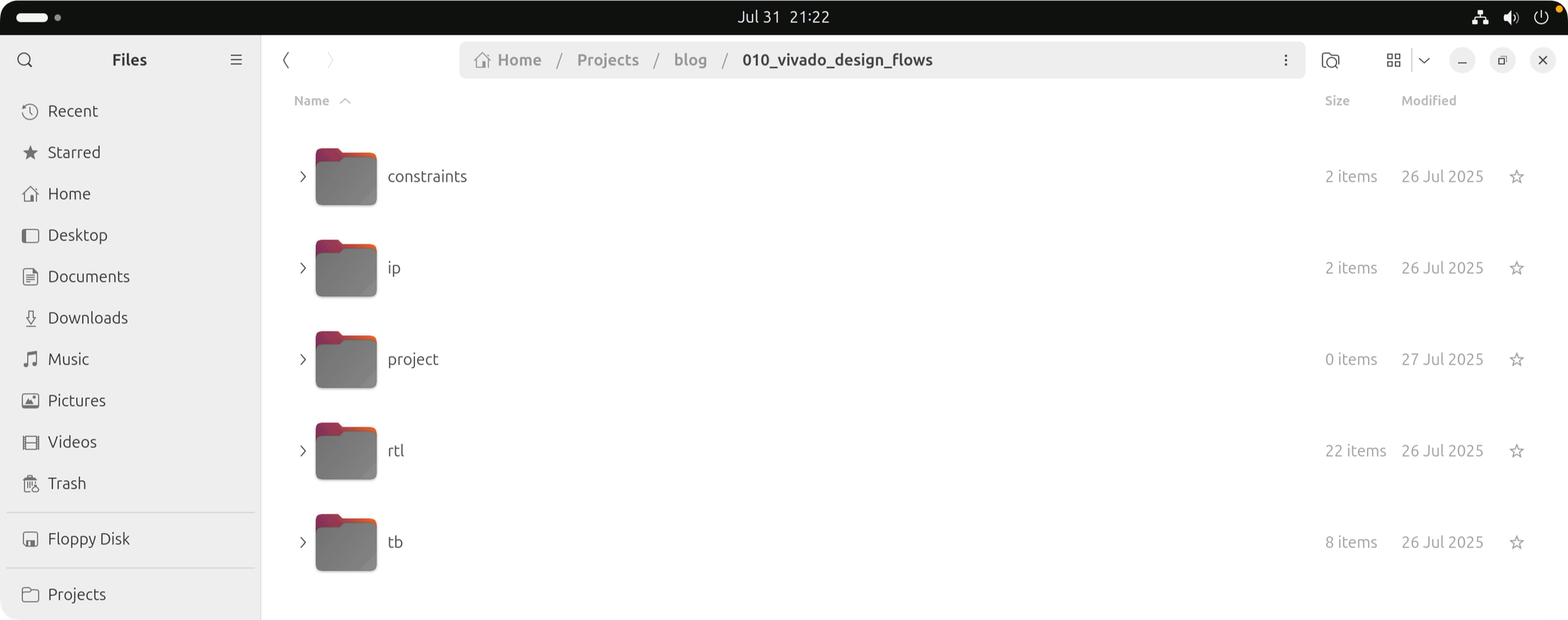
- The 'constraints' folder contains the timing and IO constraints files
- The 'ip' folder contains Vivado-specific IP design files
- The 'project' folder is initially empty; we'll use it to store our project file and as the working directory for Vivado.
- The 'rtl' folder contains the Verilog design files
- The 'tb' folder contains the simulation files
Project Mode
Now we'll create a Vivado Project using the GUI.
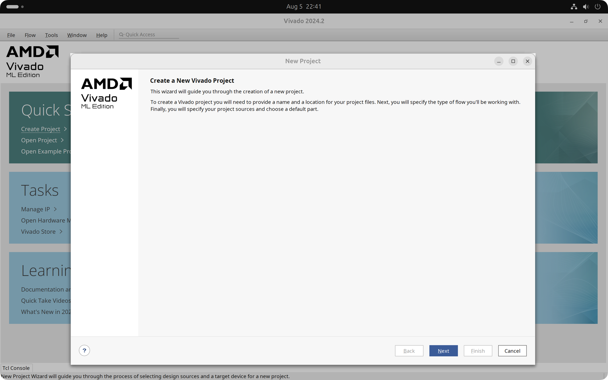
We begin by starting Vivado and selecting the 'Create Project' option from the 'Quick Start' section. The 'New Project' window opens, and we click 'Next' to start setting up our project.
- In the 'Project Name' window, we enter a name and a location for our project.
- In the 'Project Type' window, we select the 'RTL Project' option.
- In the 'Add Sources' window, we select the 'Add Files' option.
- In the 'Add Source Files' window, we click 'Add Files'. In the 'Add Source Files' window that opens, we navigate to the 'rtl' folder, select all the Verilog design sources, and click 'Ok'.
- Back in the 'Add Sources' window, we click 'Add Files' once again and navigate to the 'char_fifo' folder inside the 'ip' folder, select the 'char_fifo.xci' file, and click 'Ok'. We then repeat this process for the 'clk_core.xci' file in the 'clk_core' folder within the 'ip' directory.
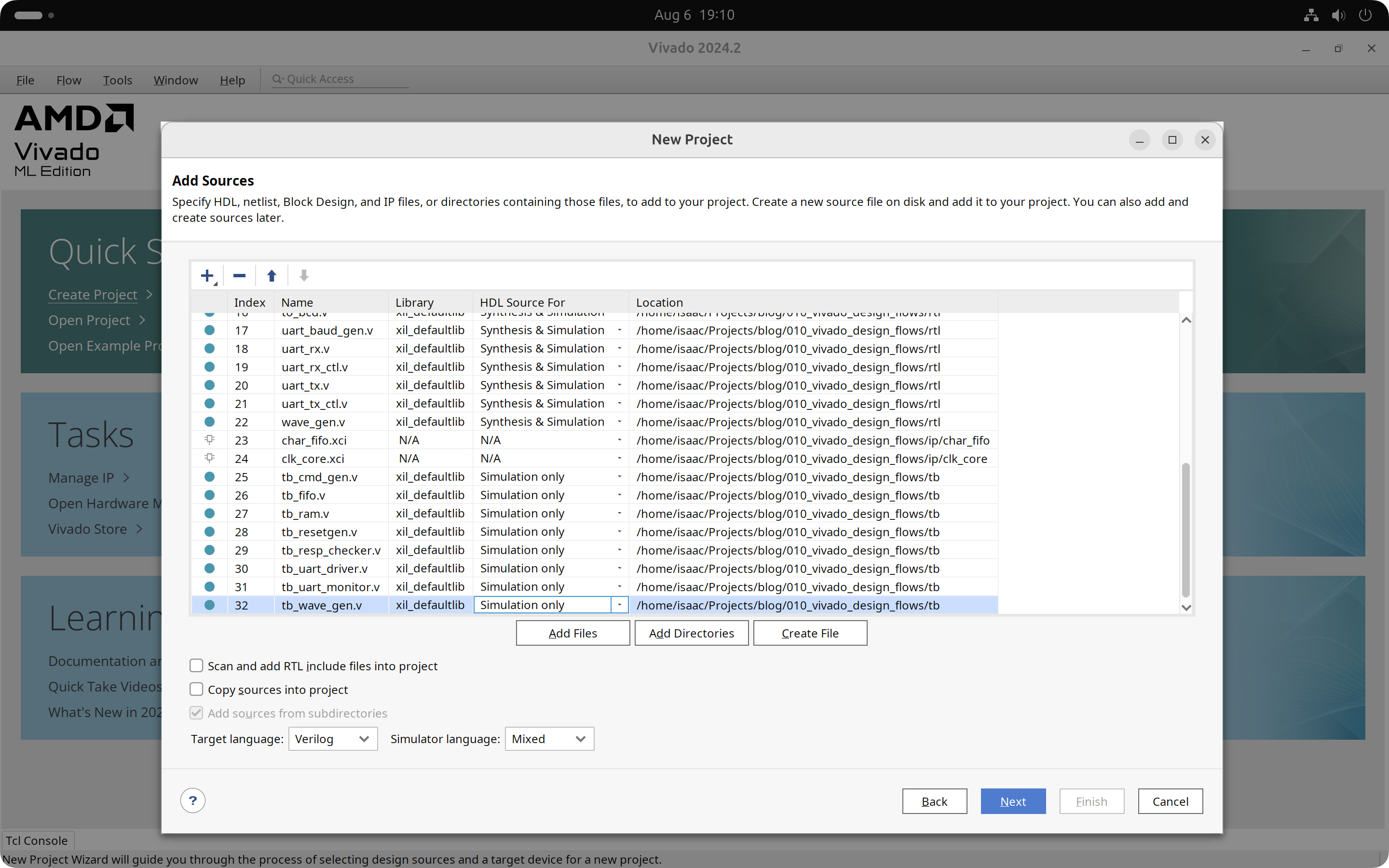
- Back in the 'Add Sources' window, we click 'Add Files' once again. In the 'Add Source Files' window that opens, we navigate to the 'tb' folder, select all the Verilog simulation sources, and click 'Ok'. This takes us back to the 'Add Sources' window, where we select all the simulation files (with the filename starting with 'tb') and set them to 'Simulation only' in the 'HDL Source For' column.
- In the 'Add Constraints (optional)' window, we click 'Add Files'. In the 'Add Constraint Files' window that opens, we navigate to the 'constraints' folder, select both .xdc files, and click 'Ok'. This takes us back to the 'Add Constraints (optional)' window, where we click 'Next'.
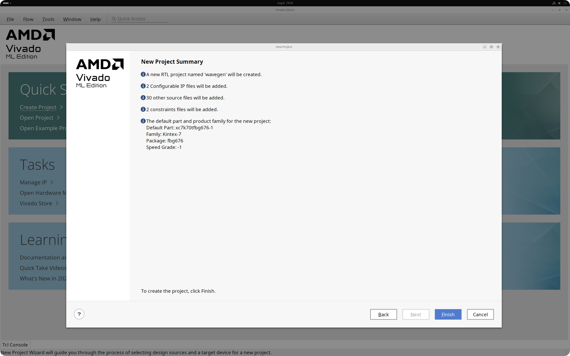
- In the 'Default Part' window, we search for the 'xc7k70tfbg676-1' device, select it, and click 'Next'.
- The 'New Project Summary' window shows the details of our new project. We click 'Finish' to create the project.
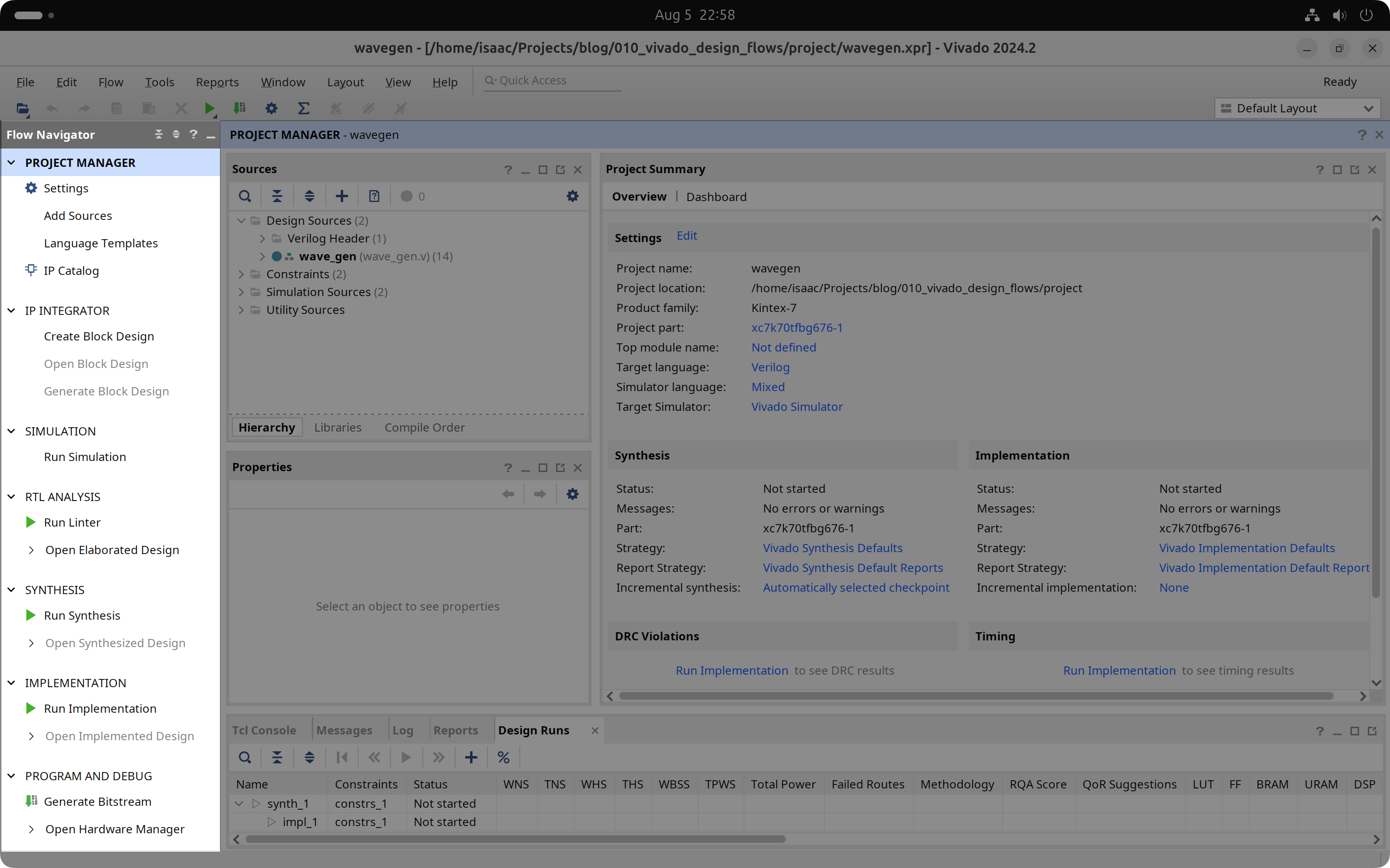
Because in Project Mode Vivado manages the design flow, the Flow Navigator on the left shows all the steps in the FPGA development process.
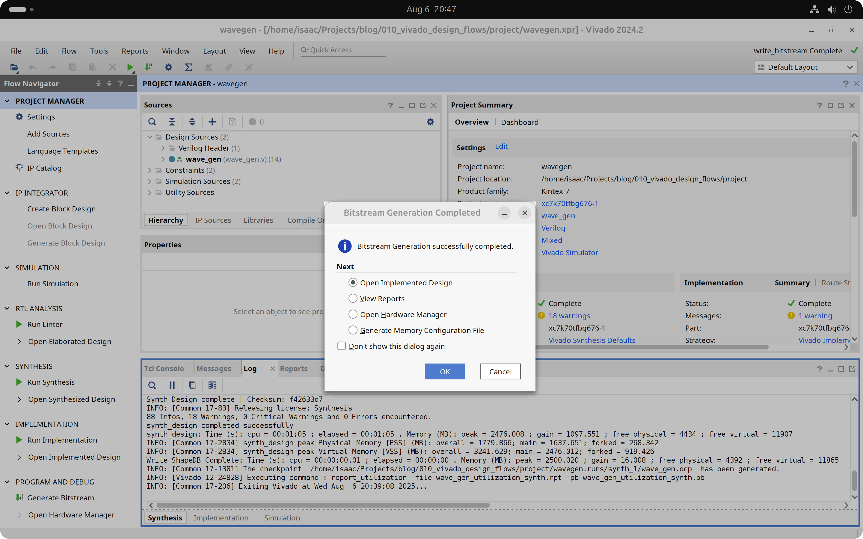
We select 'Generate Bitstream' on the bottom and click 'Yes' when Vivado asks to launch Synthesis and Implementation first. Vivado will go through the entire build process on its own, generating many intermediate files and reports along the way, and finally creating the bitstream file that we can use to program our FPGA.
In the next installment of this two-part tutorial we will recreate this project using the Non-Project Mode.
Cheers,
Isaac